Check Out The New Products from Miniature Aircraft, Kyosho, Tamiya, and JPS Aluminum Products!!! |
On October, 1998, Kyosho released a photo and data of their newest top of the line 60 class helicopter, Caliber, in Japan's R/C Technique magazine. The photo is just a shadow image of the helicopter and immediately a lot of people wanted to know more about Kyosho's upcoming flagship. They claimed the Caliber utilise lots of new designs (Kyosho claimed to have patented the design of 9 piece of part of Caliber) with emphasis to lower vibration, lower noise, ease of maintenance, and good aerobatic capabilities. On November, 1998, in a trade show, Kyosho released the Caliber. The main frame of the Caliber is a box consist of five pieces of machined aluminum in 8mm thickness, instead of the usual stack frame as found on most helicopters. Two pieces of 2mm graphite plates are used on the front of the frame for servo mounting. Control is through a three servo 120 degree ECCPM mechanism. Power from the engine is transferred through a belt first to a secondary gear that drives the main gear and the tail pinion. The main shaft measured 12mm. Power is transferred to the tail through belt, and rudder is controlled by a tail boom mounted servo with push-pull mechanism. It listed for 298,000yen in Japan (about US$2,500), and is the most expensive Japanese 60 class mass poduction helicopter ever.
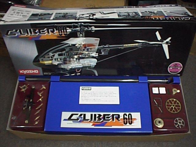
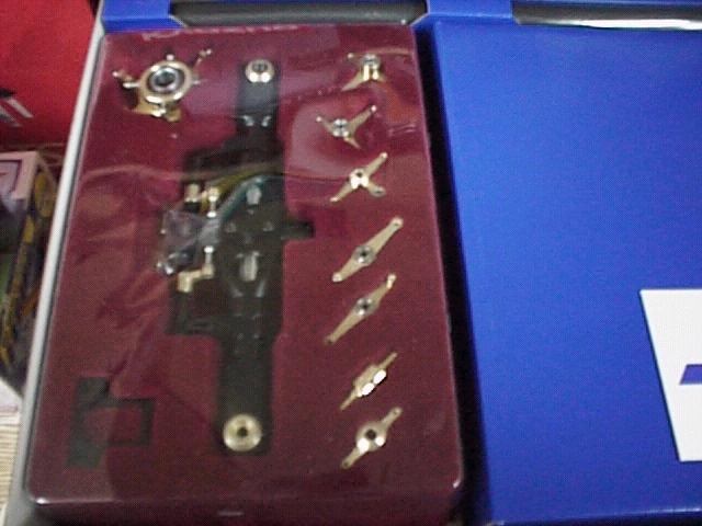
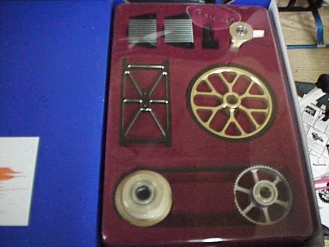
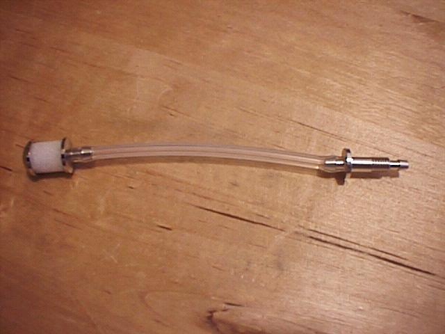
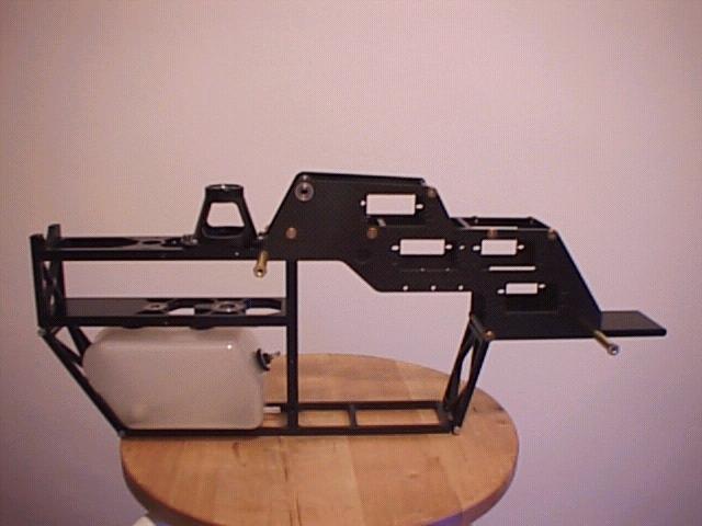
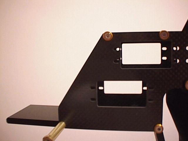
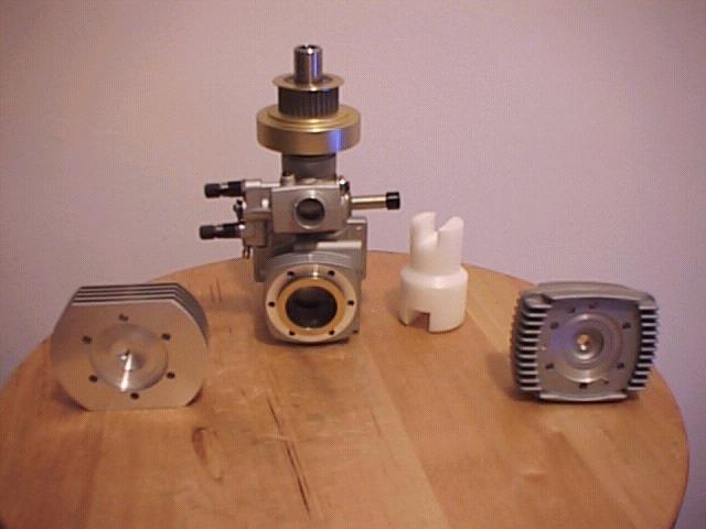
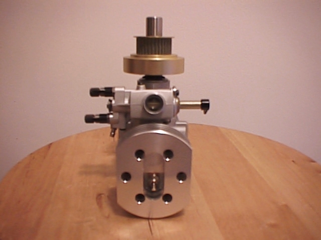
On November, 1998, when the Caliber is released, I placed an order and waited until the last day of 1998 to receive it. The box showed a photo of the Caliber, and all the unique features on the side of the box. After opening the box, my eyes widened, so is my grin. We all know that Japanese know how to package their products, but the Caliber tops all helicopters and packaged in a way that your wife would love. All major parts are packed nicely in a red velvet case, situated on both sides of the box, with a box that stored the canopy in the middle, and the tail boom in the back. All parts are either stored in the two "jewel showcases", or neatly packed in 14 bags. In fact, one of my friend's wife saw the packaging and said her husband should get one due to its packaging! I cannot resist and opened one of those "jewel box" that contained the rotor head. Kyosho must have someone professional to design the color of the Caliber, as the rotor head and the main frames are in black, and others in gold, even the decals are gold in color! Machining of the metal parts were very high quality, as commented by my friend who is a machineist. However, he also adviced that I should change the bearings on all high speed turning points cause the bearing that comes standard are inferior in quality and wears easily. I took his advice and asked him to change these bearing for me, but wondered why Kyosho nickel and dime on the Caliber. The canopy is a white FRP one,and is smooth as silk. It was a one piece design and predrilled with mounting holes. I have to paint the window in black, and Kyosho did not bother to include a shade. It was the best quality canopy that comes standard with all helicopter as far as I saw. The tail boom and tail boom support are in graphite, and the graphite fiber in these parts are woven in a smaller square than the usually seen graphite woven pattern. All pushrods are in stainless steel 2.0mm. The kit does not include main blades. Assembly Two weeks after I received the Caliber, my machineist friend finished replacing all bearing that were inferior with high quality ones made by SKF of France, NMB of Sweden, and NSK of Japan. Only the bearing themselves costed me about US$100-. The reason why I have to change the bearings was simple: to save crashes. Those bearing that comes with the Caliber are made in Thailand and Singapore, that are inferior in quality when compared to Japanese and European bearings. The Thailand and Singapore bearings wears out easily. When these bearings wears out, it leads to three problems. First, wear out bearings had plays the led to lost of precision in control and vibration. Second, during high speed operation, they will emit a very high frequency noise that jams the receiver. Third, they might disintegrate in mid flight and cause disasters. I don't mean that Japanese bearing and Europran bearings doesn't wear out, but they just last much longer. Sadly, a lot of these inferior bearings are being included standard in a lot of "top of the line" helicopter products. My friend also mentioned that the factory mounting of most bearing are pretty tight and need some special tools and skills to take them out without damaging to any part. Part I - Main frame and drive train From step 1 to step 23 dealt with the assembly of the main frame and drive train. The main frame is constructed by bolting together 10 pieces of aluminum frames and two pieces of graphite. Since all main frame bearings comes mounted by the factory, if you need to change these bearings to better quality ones, you have to change them before you assemble the main frame. For all aluminum parts of the main frame, I used stainless steel cap screws to fasten them together, and used stainless steel countersunk screws with spacers to fasten the two pieces of graphite onto the aluminum frame. When bolting together these aluminum frames, make sure that the right side is facing the right direction. The instructions sometimes did not clearly show the correct orientation of each frame. The two pieces of upper frames that also supports the gears are being secured by 3mm cap screws through collars to two pieces of horizontal frames. Since the collars are a very tight fit into the frame, when I was securing the screws, I turn all screws of each side evenly, and slowly force the collars into their slots. When fitting the base of the frame, I found a logical error of the manual. The manual said to bolt the base temporary in step 3, and then in step 15 disassemble it to mount the fuel tank. I don't see any need of this redundant step, so I went ahead to assemble the fuel tank first, and fit the tank into the main frame while I assemble the base. The fuel tank components are the best that I've ever seen by far. The fuel clunk is made of some porous material that enables fuel to be absorbed on the whole surface of the clunk. The nipple is a aluminum item, and secured to the grommet by a nut. Although the manual did not mentioned, I used some loctite to secure the nut onto the nipple. The fuel tank have four protrued "legs" that is used fit into four rubber dampers that goes into the main frame. When fitting the tank, it is best to first press the dampers into the frames before mounting the tank, cause its a very tight fit. While assembling the frame, its best to align all parts together by fasten the screws just hand tight, then after all pieces of the frame are mounted then goes back and re-tighten each screw using loctite. This is very important, at first I just screw each piece of the frame together real tight, that the last piece of the frame won't fit cause the screw opening was out of alignment, and I have to loosen up all screws to re-align the whole frame. While bolting together the aluminum pieces, I found that some screw holes have some "residue" accumulated in them to make these holes harder to be screwed in. When I encounter these holes, I screwed in a 3mm threader to clean the grooves before screw in the cap screws. There are two pieces of graphite frames that is to be fitted on the front of the main frames that act as servo mounts. The graphite frames comes pre-fitted with flanged bearings that supports the elevator arm. These graphite frames were in 2mm thickness, and the edges were smooth. Nevertheless, I rounded the edges of the frames and used thin CA to seal the edges before fitting them to the main frame. When fitting the two pieces of graphite, make sure that the flange of the bearings are facing outside. After securing the graphite pieces, the whole main frame assembly was finished.
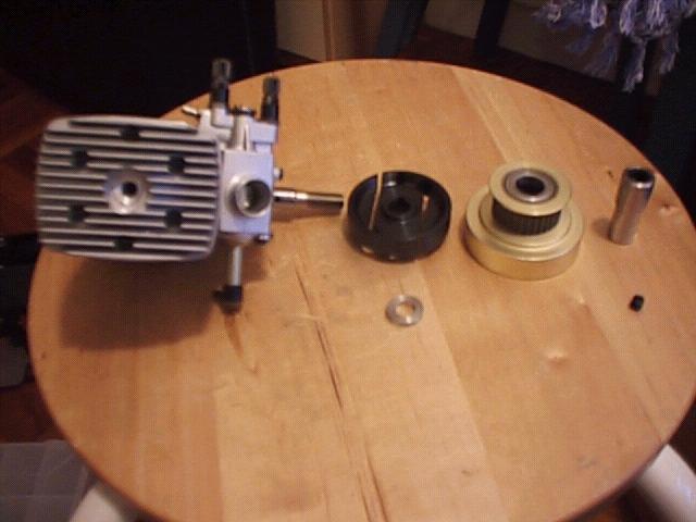
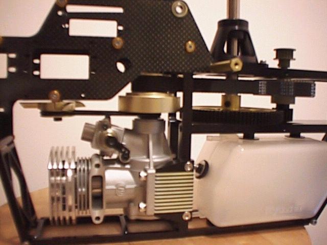
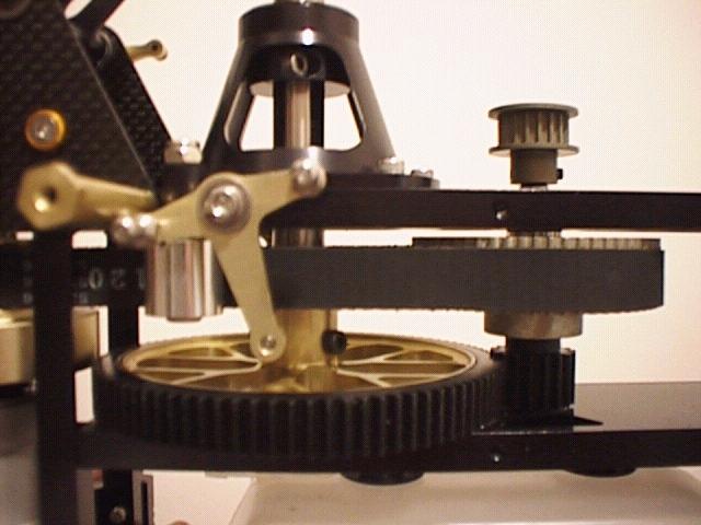
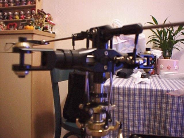
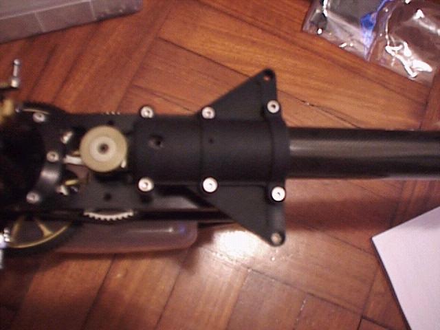
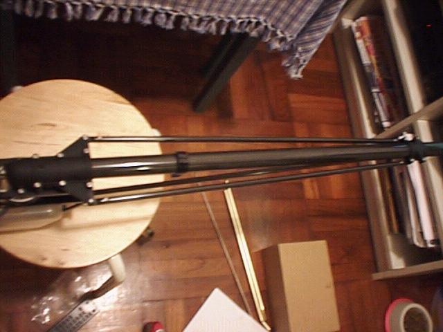
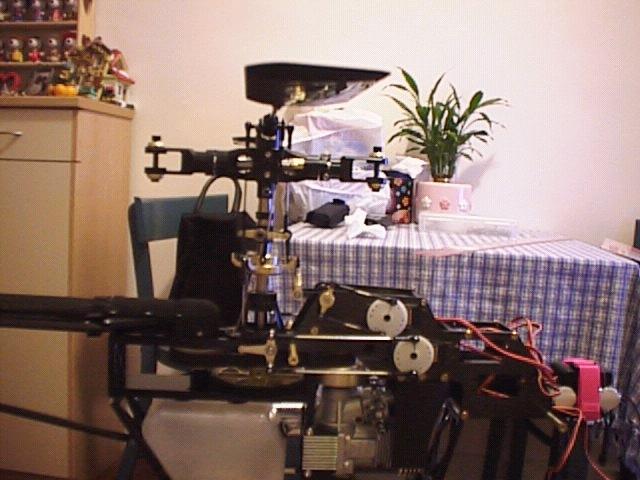
The drive train is next to be installed. The drive train runs from the clutch pinion, through a belt, to a main belt pulley. The main belt pulley then drive the tail belt pulley and the main gear pinion, then to the main gear. The main belt pulley, tail belt pulley and the main gear pinion were all fixed on to the same axle, with an one-way bearing installed inside the main belt pulley to provide autorotation. Two set screws were used to secure tail tail belt pulley and the main gear pinion to the axle. The main mast, mast stopper and main gear was installed next. The main mast measured a hefty 12mm diameter. One thing that the manual did not point out clearly was the orientation of the main mast. The mast had one hole on each end, and the one end with a 3mm hole that was farther from the end was to be mounted on to the main gear, and the end with a 4mm hole that was closer to the end was to be fitted with the rotor head. The mast stopper was fitted against the underside of the upper main mast bearing holder. The whole drive train has no gear mesh to set, and was very smooth. The drive train system provided constant tail driven autorotation mechanism, with no limited diff for adjustment. Next up was the engine installation. The clutch mechanics was a very genius design. The clutch was first slotted onto the engine shaft, held in position by the woodruff key. Next, the clutch bell was slotted on to the shaft, that was a very snug fit, and then the whole assembly was secured by the start shaft adapter that threads on to the engine's main shaft. An allen key that fit the start shaft hex opening was included. While fastening the start shaft adapter, its best to use the OS piston locking tool, and to put some loctite on the thread of the main shaft. The whole assembly was very clean, but the design of it prevented any ways to dial indicate the clutch. As a result, I had to rely on the trueness of the engine shaft and the clutch parts. Although the manual did not mention, the Caliber's powerplant can only be one that had mounting dimensions the same as OS 61 engines. I used an OS61SX/WC modified with Performance Specialties AAC piston and sleeve, and Bell Wood high compression head. I planned to use the Taya interactive carburator at first but I saved it until the engine had been broken in. The engine mount was two pieces of aluminum that clamped on to the main frame and secured by four 4mm cap screws. A big O-ring that drives the fan was slipped under the clutch for the moment. Then the engine was slipped into the opening, fitted the engine belt on to the clutch bell pulley, sit on the mounts and secured by cap screws. I used stainless steel spring washers to better prevent those mounting screws from loosening. Cooling of the engine was provided by an aluminum fan. Since the fan was spinning at a high speed, I used a High Point Balancer to balance it. The fan was mounted on to a piece of aluminum frame by a 4X20mm screw. Later, I found that the collar that slotted into the bearing of the fan had a vertical play of about 0.5mm, and that introduced high frequency vibration (More on that later). I used a Dremel tool to grind down the collar and that eliminated the play. To further strengthen the mounting of the fan, I used a 4X25mm bolt to bolt through the fan and the fan mount, and used a 4mm lock nut to lock down the screw. The whole fan assembly was secured by six 3mm screws to the main frame. It was driven by the big O-ring from the spinning clutch. The fan shroud was a one piece plastic that slips on to position with ease, and was secured by four of the screws that also secure the fan mount. While fastening the fan shroud to the main frame, be sure not to use excessive force as this will deform the bulleyes of the shroud. The fan shroud covered over 80% of the head area, so no modification was needed. The clutch assembly, engine, fan, and fan shroud mounting was the easiest amongst all other helis that I've seen too date. Next according to the instructions was to assemble the landing gear, but I left that part out until the very last.
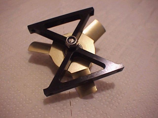
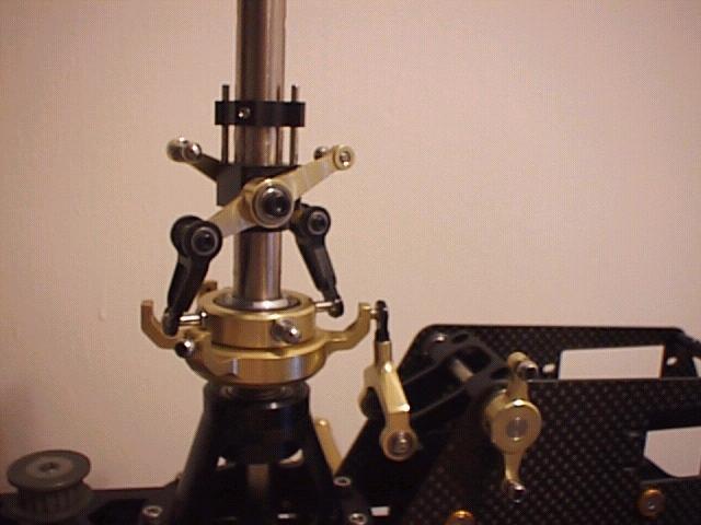
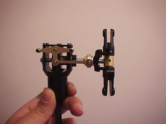
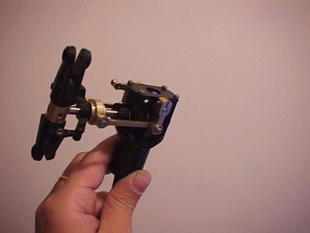
Part II - Rotor Head and Control Mechanism Since the Caliber was to be controlled by a 120degree ECCPM mechanism, so there was not to many mixing levers as with other "regular" heli. The elevator arm consisted of an A-arm that used a ball link to control the 12 o'clock point of the swashplate, and pivot on a base. The whole A-arm assembly clamped on to a shaft, with one end of the shaft held in position by an e-clip and the other end of the shaft was a push-pull bellcrank for servo control. I left the elevator arm loose for the moment since it will require adjustment later when fitting the servo and the control rod. The other two swashplate control bell cranks were identical T-shaped arm that was mounted on both sides of the frame. On the left side of the frame was a roller assembly that act as a belt tensioner. When mounting the left side t-arm, make sure to first assemble and mount the belt tensioner on to the frame before mounting the arm. The belt tensioner just touched on the engine belt, and in my opinion, did not provide enough pressure to keep the belt tension. However, I thought of no other ways to make it better at that moment, so I just do it by the instruction. The swashplate comes pre-assembled with linkage balls. The upper swashplate used some sort of hard plastic to hold the middle gimble, but I felt that the plastic might wear out easily. The washout arm assembly was two control arm that fixed on to a base, and a pair of swashplate links pivoted on the arms with two ball bearings on each arm. The washout base was ususual in that there were two guiding pins, that sticks from the base, and those pins went through the openings of the washout fixer. I found that the pins were a little bit off on the base that cause friction on the sliding of the pins through the fixer. My remedy to this was to clamp those pins on a vise, and slightly bend them to made them slide in and out of the fixer without rubbing on the inside of the slot. The rotor head came fully assembled except the flybar, but I reassembled it and changed all the bolts to stainless steel ones along the way. The main blade grips accept blades with blade root of 12mm thickness. The blade bolt was 5mm. The flybar was a 4mm stainless steel rod that goes through the top side of the rotor head. The paddles was then screwed onto the flybar, and were secured with 4mm set screws. The underside of the each paddle had to use a decal to cover half it. I wondered why the decal is used on the underside of the paddle cause it really sparkle the look of the paddle though. After assembly of the flybar, I put the whole rotor head on to a High Point Balancer to make sure the head was balanced. After the head was balanced, it was mounted onto the main mast, and secured by a 4X25mm bolt. This bolt was a garden variety 4mm metal bolt, but I would like to use a long shank one. Next is the fitting of various pushrods to the mixers and bellcranks. These pushrods were stainless steel 2mm type. I used stainless steel pushrods on all my helicopters, because they were much stronger than regular metal type, looks better, and will not rust. Since the Caliber comes standard with these, it saved me some money. On the other hand, I would like them to be 2.3mm thickness. The ball links were single sided, and the "Kyosho" logo should faced out. They were a little bit on the tight side, even after I prep them with the JR Ball Link Sizing Tool before snapping them on to the balls. I finally used some Robbe ball link lubricant to make the links more smoother.
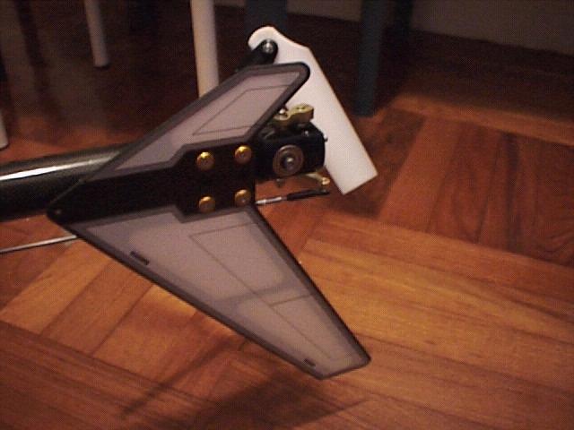
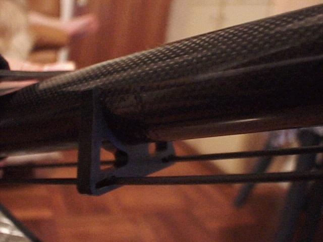
Part III - Tail The tail hub was a machined aluminum part, with blade grips in plastic. The tail blade grips were supported with two ball bearing on each side. I was a bit disappointed as there was no thrust bearing in these blade grips and fear that the movement might not be smooth during high speed turning of the tail rotor. Tle tail pitch slider was another aluminum part, with the arms in plastic, and was supported by two ball bearings. As mentioned previously, the tail was powered by a belt, so the tail gear box was pretty simple. However, the control of the tail is through a push-pull bellcrank that controls two pieces of aluminum on both the upper side and the lower side of the pitch slider. This design provided a slop free control of the tail. The whole tail gar box assembly was then slotted into the geaphite tail boom and secured by an aluminum clamp. The tail boom was constructed with a graphite pattern that is more dense as seen in regular graphite boards, and Kyosho claimed that this gave more structural support to the boom. Before mounting the tail boom to the main frame, I have to slot the two tail servo mounts on to the boom. Do not secure the tail servo mount yet cause later their position had o be adjusted when setting up the tail servo. The whole tail was then secured by two pieces of plastic parts to the main frame, and was supported by three graphite tail boom supports. The whole tail was very strong with these supports in place.
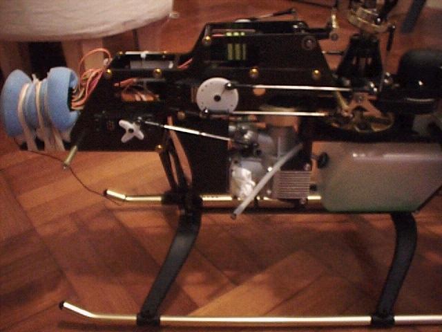
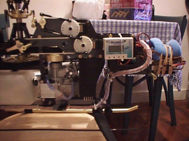
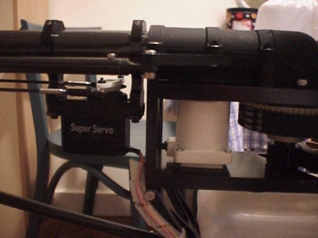
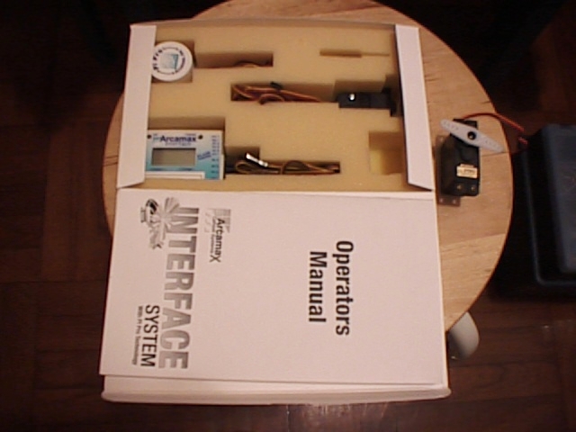
Part IV - Radio Installation and Final Bits and Pieces I used JR PCM10X with DS8201 digital servos for swashplate controls, 517 for throttle, 2700G for tail, and an Arcamax Pi Pro gyro. The DS8201 digital servos were specially designed for ECCPM controlled helicopters cause there was no mechanical limit difference between each servo, and they were very precise, so movement linearity of the swashplate was guaranteed. Servo installation were no bugger. Each servo, except the tail, was secured to the frames using 2.6mm cap screws. However, do note the orientation of the servos. All servos on the main frame should have their axles near the back of the helicopter, while the tail servo should have its axle near to the back the main frame. On the first page of the instruction, there were "FOR ADVANCED FLIERS" printed in bold. While installing the radio components, I know what that meant. For radio installation, throughout the manual there was virtually no data given as to what servo should be reversed or what were the ATV settings. Also, Kyosho clearly showed their alliance with Futaba, as in the manual all servo horn shown were Futaba ones. If you use JR, like myself, you were almost on your own. As a result, I had to set up the radio based on my experience. First, I assembled all control rods according to the length illustrated in the manual. Then, I turned on the radio, set swash (mode 65) to 120degree ECCPM operation, and set everything centerstick. Next, I had to decide what servo disc to use. For swashplate control servos, I used the big disc that comes with every super servos, and I used the outer holes that measured about 15mm from the axle as prescribed by the manual. I aligned the servo disc with control points 90degrees to the bellcrank control points, mark the holes to be used, installed the control balls, and snapped in the linkages. Finally, with the control center stick, I checked and adjusted all pushrods to make them level, and with a pitch of 6 degrees. The following data were what I used for swashplate control servos that give extreme controls without binding, and provided a pitch window of 20 degrees:
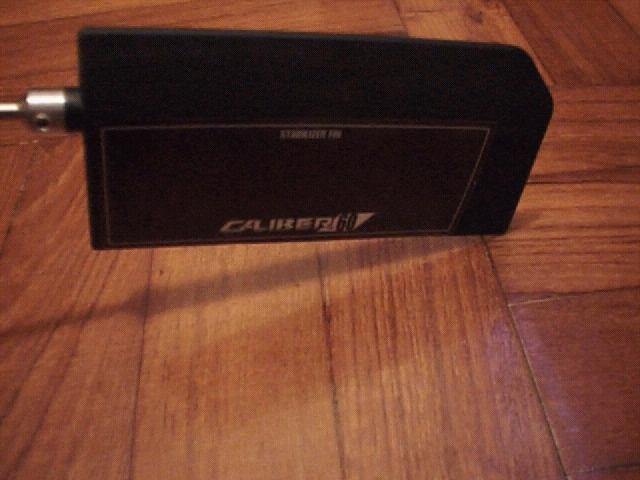
The throttle servo was installed next. I used the outmost hole of the regular "+" shaped servo horn, and it was about the same length as the outer hole of the throttle control arm. I carefully set up the middle position so that full throttle range can be covered with 100% throttle ATV. The tail servo was the last servo to be installed. The Caliber featured very interesting tail servo mounting, as the servo was suspended under the tail boom by two aluminum servo mounts. First, I connected the servo to the gyro, turn on the radio to let the servo found its neutral point, put on the extra long servo horn that comes with the 2700G, and aligned the servo horn perpendicular to the servo. Then, the servo was mounted on to the servo mount on the tail boom. Alignment of the servo had to be done first cause after mounting the servo the servo horn mounting screw will be blocked by the tail boom. Tail controls was push-pull by two graphite pushrods from the servo to the control arm of the slider. These graphite pushrods were about 1.8mm thickness, and both ends of these rods had to glue in an aluminum end that had threads. While gluing these ends to the graphite rods, I used epoxy, rather that CA as suggested by the manual. After gluing the rod ends, I checked and matched the lengths of the rods, and set them aside for the glue to cure. Then, there were three rudder linkage guides that had to be installed. They were made in soft rubbers. I really didn't like these guides as they had to be glued to the boom. I mean, one of the reasons that I liked helicopter was that I didn't have to mess around with gluing parts together. However, there were no other substitute so I glued the guides to the boom in positions according to the instruction, and once again using epoxy instead of CA. After all the glues were cured, I slotted the two graphite rods to the guides, screwed the ball links to the rod ends, and snapped on the ball links. One point that was not mentioned in the manual was the tension of these rods. After snapping the rods to the balls, slide the servo mount that stretched the rod to the extreme, and secured the mounts. These rods should be absolutely straight with no bending whatsoever, or tail control will not be precise. Finally, I set up the Arcamax Pi Pro gyro according to the instructions. Since this is the first Pi Pro that I had, and it was more complicated than my other gyros, I would follow straight to the manual and tweak the settings later. Final bits and pieces involves installation of landing gears, mufflers, blades, canopy, fins and securing receivers and routing wires. The landing gear was mounted to the main frames through four small rubber dampers. While installing these dampers, make sure that they were fully screwed in, or they will be easily damaged. For muffler, I used a K&S HN60FAI mufflers that was specially designed for the Caliber. I had been a fan of K&S mufflers cause although they cost more they provided the best mid range torque amongst other mufflers, and were very quiet. I also installed an exhaust diverter to keep the helicopter less messy. I did not install a header tank, cause I could not found a place to secure it. Will think about that later, maybe... The main rotor head accepts main blades with length up to 680mm, 12mm root and 5mm mounting holes. I planned to use Hi Products PX 60 680mm blades with the Caliber. However, at the moment that I finished the Caliber, the blades were not officially released yet. So I mounted a pair of NHP Sport II Symmetrical Carbon Blades for the moment. The PX60 blades were the "team" blades of Kyosho, and they featured a new design that used different airfoils on different sections of the blade to give all rounded performances. The canopy was one piece FRP laminated. It was the best in quality of FRP canopy that I had ever seen. Absoultely silky smooth surface, with no pot hole, seam lines or whatever that distorted the surface. However, the did not had any markings for the windows position, and a window piece was not found. Later I found that the canopy that I had was a pre-production sample, and later shipments of the Caliber will include canopies that had window markings and lexan window. My supplier also said that if I did not like my canopy I should send it back to him for exchange of the mass produced version of the canopy when they were being released. Nevertheness, I did not send the canopy back, but instead had another friend spray the window on. I am not good at spraying canopies, so I let some others that could do the job much better than myself so as not to spoil such a nice canopy. The fins were made of graphite, and decals were used to cover the openings on the fins. Once again I rounded the edges of the fins and used thin CA to seal the edges before fitting them. After about 30 hours of assembly, finally the Caliber sits in front of me, anxiously waiting to leap into the sky. I checked the CG and it was a little bit forward, due to the high capacity battery that I used. Dry weight was a tad under 4,650 grams, and it was the lightest 60 class heli that I had. I thought my Kalt Omega Zeus was light enough, and the Caliber top that by almost 200g.
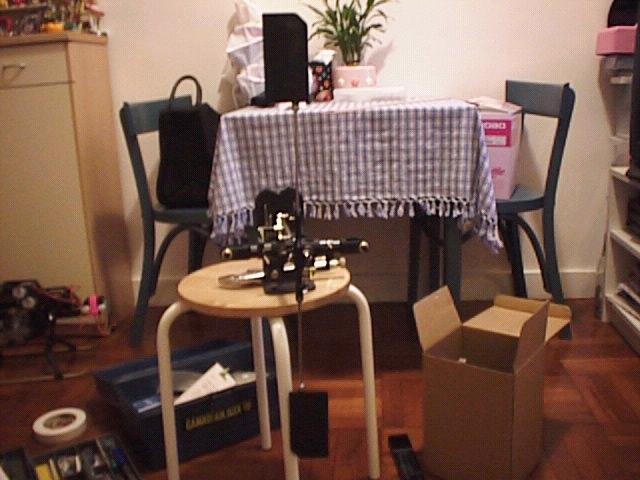
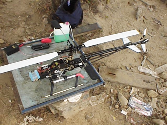
First Flight The first day when I brought the Caliber to the field, everyone there was having a discussion about it. I know that several guys would like to see how it flew before considering one for themselves. Everyone was pushing me to fly the Caliber, but my ritual with new engine was to always idle it for two full tanks to break in the engine before taking it to the sky. So I filled the first tank of fuel, and started the engine. At the click of the starter, the engine started, but immediately I knew something was wrong. The frame of the Caliber was vibrating at a very high pitch when the engine was on idle. At first, I thought it was due to the idle needle not set, but after tweaking the idle needle, the vibration still remained. The vibration was so severe that even touching the needles of the engine gave an itching feeling to the finger. So, without finish burning the first tank of fuel, I stopped the engine and called a quit for the day. I thought to myself, these vibrations must had come from some high speed turning parts, and during idle the only high speed trning parts were the clutch and the fan. Since the design of the clutch prevented dial indicating, I hoped it must be something wrong with the fan, or the whole clutch mechanism was defective and was not 100% centered. At home, I disassembled the fan assembly, and found that the collar of the fan was giving play. I fixed that immediately, and hoped that was the problem that caused the vibration. Second Flight and On The second day I brought the Caliber back to the field, and started the engine. The vibration was gone. I slipped a finger into the fan shroud to sense the air from the fan, and felt that the air current might not be enough to provide adequate cooling to the engine. Some modifications had to be done on the fan before summer, I thought, cause summer in Hong Kong were usually in high 90s with humidity also in high 90%, and if cooling was not enough it will sure kill the engine. After idling for two full tanks of fuel, I hovered the Caliber to set the trims, checked for tracking, and set the head speed. I set the head speed on around 1,400rpm for hovering. There were no apparant shakes, wobbles or vibrations. Then I started to do some hovering manuovers. Hovering was rock solid, and with all the belts that drove various gears, and coupled with a very silent muffler, it was almost like flying a helicopter with 4 cycle engine. I then tried some "hover cuts" to test the auto-rotation capabilities, and it showed that it had plenty of reserve, far more than the Kalt Omega Zeus that I thought was the best auto-rotation performer. I guess the weight factor and the constant driven tail did contribute to the sparkling auto-rotation performance. Next few tanks of fuel was to set the idle ups and test the aerobatics capabilities of the Caliber. For aerobatics, I set the head speed to around 1,800rpm. Vertical climbing of the Caliber was second to none, and even with the engine on the rich side it seemed that it wanted to punch a hole in the sky. Fast forward flight was fast and tracked straight. I could throw whatever manuovers at the Caliber and it will reply to me with a very good result. The tail was very powerful, and it will hold wherever I put the rudder at neutral. However, cyclic response was adequate for F3C manuovers, and 3D pilots would want faster response. Anyway, I went home that day with a smile.
Final Thoughts If you asked me whether the Caliber worth its cost, I will tell you no. Although it performed very well, I still felt that it was overpriced. Yes, a lot of people would like to own a Ferrari, but with a fraction of the price a Toyota Supra can still be as fast. A US$2,500 helicopter sure will be hard for a lot of people's budget. Also, eventhough Kyosho touted that the Caliber will be the best 60 class helicopter when it was released, I felt that there was something Kyosho could do to make it better, with the price being first, bearings being next, and instructions being third. With the competition of the "Flagship" 60 class helicopter becoming fierce, and the world economy was going down, Kyosho had better come up with more for the Caliber to make it a true flagship. I will let you know about any new developments of my Caliber in this page ASAP. Any questions/comment please contact jasonchan@mail.infoease.com. |

Last
Updated on 01/01/1999 - Over |
Need
a computer??? |
![]() Powered By
Powered By ![]()